• Good coding style means that the synthesis tool can identify constructs within your code that it can easily map to technology features.
• All programmable devices may have their unique architectural resources e.g. Xilinx Virtex series has built-in RAM.
• Coding for performance :
– common mistake is to ignore hardware and start coding as if programming. To achieve best performance the designer must think about hardware.
• Improve performance by
– avoiding unnecessary priority structures in logic.
– optimizing logic for late arriving signals.
– structuring arithmetic for performance.
– avoiding area inefficient code.
– buffering high fan-out signals.
• Use “constants” to enhance readability and code maintenance.
• Comparison with a constant is preferred since it is much “cheaper” to implement.
• To avoid accidental latches
– specify all clauses of “if” and “case” statements.
– specify all outputs.
• Use “case” rather than “if-then-else” whenever possible.
• Use parentheses for better operation.
• Never use mode “buffer”
information shared by www.irvs.info
IRVS VLSI IDEA INNOVATORS
VLSI Project, Embedded Project, Matlab Projects and courses with 100% Placements
Monday, January 31, 2011
Friday, January 28, 2011
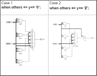
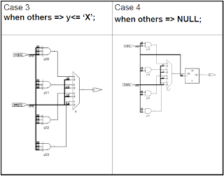
Multiplexer optimization
The hardware inferred depends on the condition given in the “when others” clause
case sel is
when “000” => y<= data(0);
when “001” => y<= data(1);
when “010” => y<= data(2);
when “011” => y<= data(3);
1) when others => y<= ‘0’;
2) when others => y<= ‘Z’;
3) when others => y<= ‘X’;
4) when others => NULL;
end case;
information shared by www.irvs.info
case sel is
when “000” => y<= data(0);
when “001” => y<= data(1);
when “010” => y<= data(2);
when “011” => y<= data(3);
1) when others => y<= ‘0’;
2) when others => y<= ‘Z’;
3) when others => y<= ‘X’;
4) when others => NULL;
end case;


information shared by www.irvs.info
Thursday, January 27, 2011
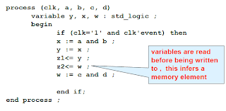
Using Signals or Variables
• Variables are used only for convenience of describing behaviour.
• Variables are used and declared in a process however it cannot be used to communicate between processes.
• Variable assignments are done immediately and are executed sequentially.
• Variables may or may not represent physical wires.
• Signal assignments are done at the end of process.
• Signals represent physical wires in the circuit.
• Use variables in combinational processes because there is less simulation overhead.
• Order dependency
– Signal assignments are order independent.
– Variable assignments are order dependent.
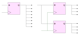
– Signal assignments under a clocked process are translated into registers.
– Variable assignments under a clocked process may or may not be translated into registers.
Signals or Variables
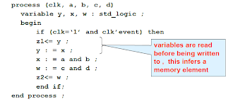
Hardware inferred
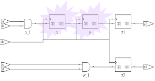
Same process with order of statements changed
Hardware inferred
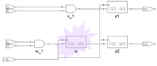
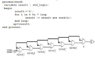
Hardware modeling examples “For loop”
information shared by www.irvs.info
• Variables are used and declared in a process however it cannot be used to communicate between processes.
• Variable assignments are done immediately and are executed sequentially.
• Variables may or may not represent physical wires.
• Signal assignments are done at the end of process.
• Signals represent physical wires in the circuit.
• Use variables in combinational processes because there is less simulation overhead.
• Order dependency
– Signal assignments are order independent.
– Variable assignments are order dependent.
– Signal assignments under a clocked process are translated into registers.
– Variable assignments under a clocked process may or may not be translated into registers.
Signals or Variables

Hardware inferred

Same process with order of statements changed

Hardware inferred

Hardware modeling examples “For loop”

information shared by www.irvs.info
Tuesday, January 25, 2011
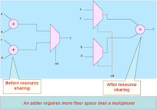
Resource Sharing
• Some synthesis tools automatically perform a limited amount of resource sharing ( for arithmetic expressions that are mutually exclusive).
• Consider the code:
ADDSEL: process( sel, a ,b,c,d)
begin
if (sel=‘1’ ) then
y<= a + b ;
else
y<= c + d ;
end if ;
end process ADDSEL ;
Simulation vs. Synthesis
• Some simulation constructs are not supported by synthesis tools.
– e.g. wait statements.
• Synthesis tools ignore initial values.
• Care should be taken so that simulation- synthesis mismatch does not occur.
information shared by www.irvs.info
• Consider the code:
ADDSEL: process( sel, a ,b,c,d)
begin
if (sel=‘1’ ) then
y<= a + b ;
else
y<= c + d ;
end if ;
end process ADDSEL ;

Simulation vs. Synthesis
• Some simulation constructs are not supported by synthesis tools.
– e.g. wait statements.
• Synthesis tools ignore initial values.
• Care should be taken so that simulation- synthesis mismatch does not occur.
information shared by www.irvs.info
Monday, January 24, 2011
Synthesis Tool
Expectations
A good synthesis tool should
– perform technology specific optimizations i.e. vendor specific FPGAs and CPLds.
– have best optimization techniques.
– allow designer control.
– have broad language coverage.
– provide user friendly debugging environment.
– have fast compile times.
– provide clean and seamless link with back end tools.
Features
Tool cost depends on features provided by it
Desirable features are:
– Replicating the logic.
– Duplicate flip-flops, remove unused logic.
– optimization across design hierarchy.
– resource sharing of adders , incrementors, multipliers.
– automatic RAM inference (RAM logic is automatically mapped to technology specific RAM cells).
Replicate logic
– Replicate logic to meet fan-out demands.
– E.g. WR’ may be connected to 100 points hence add buffers to split internally.
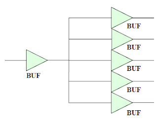
Duplicating logic
• We can duplicate the logic which generates the signal , for minimizing fan-out.
• Trade-off : Loading effect of signals is reduced hence lowering propagation delay but at the cost of logic and interconnect complexity.
information shared by www.irvs.info
A good synthesis tool should
– perform technology specific optimizations i.e. vendor specific FPGAs and CPLds.
– have best optimization techniques.
– allow designer control.
– have broad language coverage.
– provide user friendly debugging environment.
– have fast compile times.
– provide clean and seamless link with back end tools.
Features
Tool cost depends on features provided by it
Desirable features are:
– Replicating the logic.
– Duplicate flip-flops, remove unused logic.
– optimization across design hierarchy.
– resource sharing of adders , incrementors, multipliers.
– automatic RAM inference (RAM logic is automatically mapped to technology specific RAM cells).
Replicate logic
– Replicate logic to meet fan-out demands.
– E.g. WR’ may be connected to 100 points hence add buffers to split internally.

Duplicating logic
• We can duplicate the logic which generates the signal , for minimizing fan-out.
• Trade-off : Loading effect of signals is reduced hence lowering propagation delay but at the cost of logic and interconnect complexity.

information shared by www.irvs.info
Saturday, January 22, 2011
Synthesis Issues
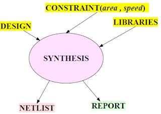
What is synthesis ?
• Synthesis is an automatic process that converts user’s hardware description into structural logic description.
• When we use VHDL as textual file, the process is called VHDL Synthesis.
• Synthesis is a means of converting HDL into real world hardware.
• Synthesis tools generate a gate-level netlist for the target technology.
• Synthesis is target device technology specific.
• Synthesizer will try to use the best architectural resource available with the target.
Several steps work out behind the scene!
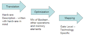
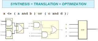
• Translation ( language synthesis ) : Design at higher level of description is compiled into known language elements.
• Optimization : Algorithms are applied to make the design compact and fast.
• Design is mapped using architecture specific techniques.
Synthesis process – design flow
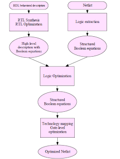
Synthesis process
• Translation : Inputs are transformed into a description based Boolean equations.
– If the input data consists of gate level netlist then it is necessary to extract Boolean equations to determine functionality of all used gates.
• Technology independent logic optimization: This process aims to improve structure of Boolean equations by applying rules of Boolean algebra . This removes the redundant logic and reduces the space requirement.
• Technology Mapping: This is the process of transforming technology independent netlist into technology dependent one. During mapping , timing and area information of all usable gates of the target technology must be available. It is split into two phases.
– Flattening
– Structuring
Flattening
• The aim is to generate Boolean equations for each output of module in such a way that the output value is a direct function of inputs. These equations reflect two level logic in SOP form.
• Resulting equations do not imply any structure.
• Good optimization results are obtained.
• Caution: In case of structured logic this process would destroy the characteristic structure and its associated properties . e.g. carry look ahead adder.
• Flattening cannot be applied to every logic circuit because the number of product terms may become very large.
Structuring
• New intermediate variables are inserted during the structuring process.
• E.g. If (A’.B’.C’) occurs 10 times then the tool may assign X= (A’.B’.C’) and use X everywhere.
• Finally , the sub-functions are substituted into original equations.
• Compared to the logic before structuring, the resulting area is reduced.
Synthesis process- review
• Translation process converts RTL to a Boolean form.
• Optimization is done on the converted Boolean equations.
• Optimized logic is mapped to technology library.
• Flattening is a process where all the design hierarchy is removed, the entire design is transformed into a flat , generic , SOP form.
• Structuring is the opposite of flattening, its adds structure to the generic design by extracting common logic factors and representing them as intermediate nodes to produce compact logic.
information shared by www.irvs.info
• Synthesis is an automatic process that converts user’s hardware description into structural logic description.
• When we use VHDL as textual file, the process is called VHDL Synthesis.
• Synthesis is a means of converting HDL into real world hardware.
• Synthesis tools generate a gate-level netlist for the target technology.

• Synthesis is target device technology specific.
• Synthesizer will try to use the best architectural resource available with the target.
Several steps work out behind the scene!

• Translation ( language synthesis ) : Design at higher level of description is compiled into known language elements.
• Optimization : Algorithms are applied to make the design compact and fast.
• Design is mapped using architecture specific techniques.
Synthesis process – design flow

Synthesis process
• Translation : Inputs are transformed into a description based Boolean equations.
– If the input data consists of gate level netlist then it is necessary to extract Boolean equations to determine functionality of all used gates.
• Technology independent logic optimization: This process aims to improve structure of Boolean equations by applying rules of Boolean algebra . This removes the redundant logic and reduces the space requirement.
• Technology Mapping: This is the process of transforming technology independent netlist into technology dependent one. During mapping , timing and area information of all usable gates of the target technology must be available. It is split into two phases.
– Flattening
– Structuring
Flattening
• The aim is to generate Boolean equations for each output of module in such a way that the output value is a direct function of inputs. These equations reflect two level logic in SOP form.
• Resulting equations do not imply any structure.
• Good optimization results are obtained.
• Caution: In case of structured logic this process would destroy the characteristic structure and its associated properties . e.g. carry look ahead adder.
• Flattening cannot be applied to every logic circuit because the number of product terms may become very large.
Structuring
• New intermediate variables are inserted during the structuring process.
• E.g. If (A’.B’.C’) occurs 10 times then the tool may assign X= (A’.B’.C’) and use X everywhere.
• Finally , the sub-functions are substituted into original equations.
• Compared to the logic before structuring, the resulting area is reduced.
Synthesis process- review

• Translation process converts RTL to a Boolean form.
• Optimization is done on the converted Boolean equations.
• Optimized logic is mapped to technology library.
• Flattening is a process where all the design hierarchy is removed, the entire design is transformed into a flat , generic , SOP form.
• Structuring is the opposite of flattening, its adds structure to the generic design by extracting common logic factors and representing them as intermediate nodes to produce compact logic.
information shared by www.irvs.info
Friday, January 21, 2011
Testbench

Waveforms

Testbench : Using assert…report

Waveforms

Error Report

SUMMARY
• A Test bench thus is an effective built- in tool for verifying VHDL designs.
• Troubleshooting becomes easier and faster because of the ASSERT…REPORT clause.
• Automation of verification is possible because of the seamless integration of language elements.
information shared by www.irvs.info
Thursday, January 20, 2011
Using Test Benches
• The design must be verifiable.
• It is much more convenient to use a test bench for design verification.
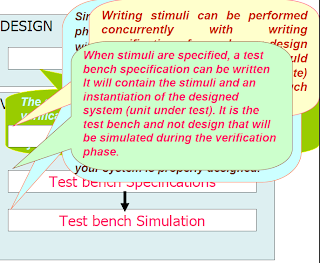
• Writing a test bench -> very complex task.
• Therefore some guidelines for future stimuli development should be written as you progress with the design.
• It is the test bench which is simulated, not the unit under test.
• The UUT is only one of the components instantiated in a test bench.
• There is no limitation on the test bench size.
• The only limitation is the VHDL simulator used capability.
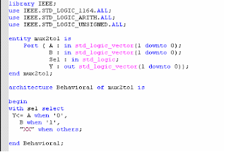
Example : Multiplexer
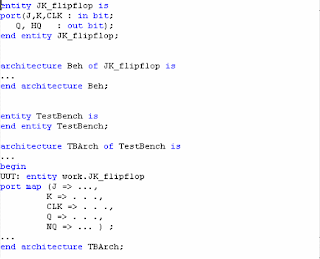
Example : J-K FlipFlop
Closer look at Testbench
UUT: 2- bit Multiplexer
information shared by www.irvs.info
• It is much more convenient to use a test bench for design verification.
• Writing a test bench -> very complex task.
• Therefore some guidelines for future stimuli development should be written as you progress with the design.
• It is the test bench which is simulated, not the unit under test.
• The UUT is only one of the components instantiated in a test bench.
• There is no limitation on the test bench size.
• The only limitation is the VHDL simulator used capability.

Example : Multiplexer

Example : J-K FlipFlop

Closer look at Testbench
UUT: 2- bit Multiplexer

information shared by www.irvs.info
Wednesday, January 19, 2011
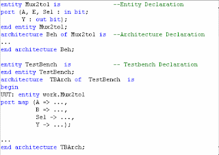
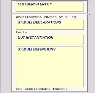
Elements of a VHDL Test Bench
• A VHDL test bench is just another specification with its own.
• entity
• architecture
• In addition, it has special structure with some elements that are characteristic to this type of specification:
• Test bench entity has no ports,
• UUT component instantiation - the relationship between the test bench and UUT is specified through component instantiation and structural-type specification,
• Stimuli - it is a set of signals that are declared internally in the test bench architecture and assigned to UUT's ports in its instantiation. The stimuli are defined as waveforms in one or more behavioral processes.
information shared by www.irvs.info
• entity
• architecture
• In addition, it has special structure with some elements that are characteristic to this type of specification:
• Test bench entity has no ports,
• UUT component instantiation - the relationship between the test bench and UUT is specified through component instantiation and structural-type specification,
• Stimuli - it is a set of signals that are declared internally in the test bench architecture and assigned to UUT's ports in its instantiation. The stimuli are defined as waveforms in one or more behavioral processes.

information shared by www.irvs.info
Tuesday, January 18, 2011
Test benches in VHDL
Introduction
• A design is always incomplete without verification.
• There are several ways to verify VHDL designs.
• Test benches are one of them.
• Test benches are also called Test cases.
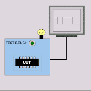
• A Test bench is an environment, where a design ( called design or unit under test UUT) is checked.
– applying signals (stimuli).
– monitoring its responses by signal probes and monitors.
• A testbench substitutes the design’s environment in such a way that the behaviour of the design can be observed and analyzed.
A test bench always consists of following elements:
– a socket for the unit under test (UUT).
– a stimuli generator (a subsystem that applies stimuli to UUT, either generating them internally or reading from an external source).
– tools for observing UUT responses to the stimuli.
Concept of Test bench
information shared by www.irvs.info
• A design is always incomplete without verification.
• There are several ways to verify VHDL designs.
• Test benches are one of them.
• Test benches are also called Test cases.
• A Test bench is an environment, where a design ( called design or unit under test UUT) is checked.
– applying signals (stimuli).
– monitoring its responses by signal probes and monitors.
• A testbench substitutes the design’s environment in such a way that the behaviour of the design can be observed and analyzed.
A test bench always consists of following elements:
– a socket for the unit under test (UUT).
– a stimuli generator (a subsystem that applies stimuli to UUT, either generating them internally or reading from an external source).
– tools for observing UUT responses to the stimuli.
Concept of Test bench

information shared by www.irvs.info
Thursday, January 13, 2011
TYPES OF SIMULATION
• FUNCTIONAL SIMULATION
• BEHAVIORAL SIMULATION
• STATIC TIMING SIMULATION
• GATE-LEVEL SIMULATION
• SWITCH-LEVEL SIMULATION
• TRANSISTOR-LEVEL OR CIRCUIT- LEVEL SIMULATION
• FUNCTIONAL SIMULATION
It ignores timing aspects.
Verifies only the functionality of the design.
• BEHAVIORAL SIMULATION
A given functionality is modeled using HDL.
Timing aspects are considered.
• STATIC TIMING SIMULATION
A built in tool that computes delay for each timing path
Does not require input stimuli.
• GATE-LEVEL SIMULATION
Is used to check the timing performance of design
Delay parameters of logic cells are used to verify things.
• SWITCH-LEVEL SIMULATION
Is one level below the gate level simulation.
It models transistors as switches.
It provides more accurate timing predictions than gate-level simulation.
• TRANSISTOR-LEVEL SIMULATION
Requires transistor models. Circuit is described in terms of resistances, capacitances and voltage and current sources.
A set of mathematical equations relating current and voltages is setup and solved numerically.
Gives analog results and is most accurate.
Requires large amount of computing resources.
Simulation time depends on :
• Simulation levels of logic
• Physical Memory of PC
• Speed of PC
information shared by www.irvs.info
• BEHAVIORAL SIMULATION
• STATIC TIMING SIMULATION
• GATE-LEVEL SIMULATION
• SWITCH-LEVEL SIMULATION
• TRANSISTOR-LEVEL OR CIRCUIT- LEVEL SIMULATION
• FUNCTIONAL SIMULATION
It ignores timing aspects.
Verifies only the functionality of the design.
• BEHAVIORAL SIMULATION
A given functionality is modeled using HDL.
Timing aspects are considered.
• STATIC TIMING SIMULATION
A built in tool that computes delay for each timing path
Does not require input stimuli.
• GATE-LEVEL SIMULATION
Is used to check the timing performance of design
Delay parameters of logic cells are used to verify things.
• SWITCH-LEVEL SIMULATION
Is one level below the gate level simulation.
It models transistors as switches.
It provides more accurate timing predictions than gate-level simulation.
• TRANSISTOR-LEVEL SIMULATION
Requires transistor models. Circuit is described in terms of resistances, capacitances and voltage and current sources.
A set of mathematical equations relating current and voltages is setup and solved numerically.
Gives analog results and is most accurate.
Requires large amount of computing resources.
Simulation time depends on :
• Simulation levels of logic
• Physical Memory of PC
• Speed of PC
information shared by www.irvs.info
DELAY MODELING
Delays are timing parameters given by the user for modeling physical characteristics of hardware.
Delays are specified in signal assignment statements only.
Delays should NOT be used in variable assignments.
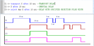
INERTIAL DELAY
• It is used to model the inherent inertia of physical devices.
• Example:
– The input value must be stable for a specified minimum pulse duration before the value is allowed to propagate to the output.
– If the input is not stable for the specified limit, no output change occurs.
TRANSPORT DELAY
• It represents pure propagation delay i.e., wires and interconnect delays.
• Signal value is assigned with a specified delay independent of the width of the input waveform.
DELAYS
information shared by www.irvs.info

Delays are specified in signal assignment statements only.
Delays should NOT be used in variable assignments.
INERTIAL DELAY
• It is used to model the inherent inertia of physical devices.
• Example:
– The input value must be stable for a specified minimum pulse duration before the value is allowed to propagate to the output.
– If the input is not stable for the specified limit, no output change occurs.
TRANSPORT DELAY
• It represents pure propagation delay i.e., wires and interconnect delays.
• Signal value is assigned with a specified delay independent of the width of the input waveform.
DELAYS

information shared by www.irvs.info
Subscribe to:
Comments (Atom)