IRVS VLSI IDEA INNOVATORS

IRVS VLSI IDEA INNOVATORS
VLSI Project, Embedded Project, Matlab Projects and courses with 100% Placements

Monday, November 29, 2010

Case statement

• CASE is another statement intended exclusively for sequential code.

• The CASE statement (sequential) is very similar to WHEN (combinational).

• All permutations must be tested, so the keyword OTHERS is often helpful.

• Another important keyword is NULL (the counterpart of UNAFFECTED), which should be used when no action is to take place.

• CASE allows multiple assignments for each test condition while WHEN allows only one.

Syntax

[Label:] case Expression is
when Choices =>
SequentialStatements...
when Choices =>
SequentialStatements...
... {any number of when parts}
end case [Label];

Choices = Choice | Choice | ...
Choice = {either}
Constant Expression
Range
others {the last branch}


Where


process – begin - - end
function – begin - - end
procedure – begin - - end
if – then - - elsif – then - - else - - end
case - => - - when - => - - end
loop--end


Rules

• The Expression must not be enclosed in parenthesis.

• The type of the Expression must be enumeration, integer, physical, or a one
dimensional array.

• Every case of the Expression must be covered once and only once by the
Choices.


Synthesis

• Assignments within case statements generally synthesize to multiplexers.

• Incomplete assignments (i.e. where outputs remain unassigned for certain input conditions) in unclocked processes synthesize to transparent latches.

• Incomplete assignments in clocked processes synthesize to recirculation around registers.

Example

case ADDRESS is
when 0 =>
-- Select a single value
A <= '1';
when 1 =>
A <= '1'; -- More than one statement in a -- branch
B <= '1';
when 2 to 15 => -- Select a range of ADDRESS -- values
C <= '1';
when 16 | 20 | 24 => -- Pick out several -- ADDRESS values
B <= '1';
C <= '1';
D <= '1';
when others =>
-- Mop up the rest
null;
end case;


information shared by www.irvs.info
Friday, November 26, 2010

Wait statement

• The operation of WAIT is sometimes similar to that of IF.

• PROCESS cannot have a sensitivity list when WAIT is employed.

• Three flavours of WAIT statements are:

– WAIT UNTIL
– WAIT ON
– WAIT FOR


Syntax

WAIT UNTIL signal_condition;

• The WAIT UNTIL statement accepts only one signal, thus being more appropriate for synchronous code than asynchronous.

• Since the PROCESS has no sensitivity list in this case, WAIT UNTIL must be the first statement in the PROCESS.

• The PROCESS will be executed every time the condition is met.

Example ( 8-bit register )

PROCESS -- no sensitivity list
BEGIN
WAIT UNTIL (clk'EVENT AND clk='1');
IF (rst='1') THEN
op <= "00000000";
ELSIF (clk'EVENT AND clk='1') THEN
op <= inp;
END IF;
END PROCESS;


Output and Inference


Syntax

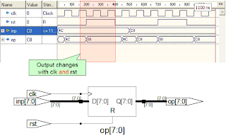
WAIT ON signal1 [, signal2, ... ];

• The WAIT ON statement accepts multiple signals.

• The PROCESS is put on hold until any of the signals listed changes.

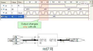
Example ( 8-bit register )

PROCESS
BEGIN
WAIT ON clk, rst;
IF (rst='1') THEN
op <= "00000000";
ELSIF (clk'EVENT AND clk='1') THEN
op <= inp;
END IF;
END PROCESS;


Output and Inference


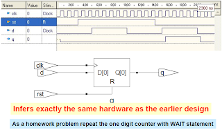
DFF revisited with WAIT!

LIBRARY ieee;
USE ieee.std_logic_1164.all;
ENTITY dff IS
PORT (d, clk, rst: IN STD_LOGIC; q: OUT STD_LOGIC);
END dff;
ARCHITECTURE dff OF dff IS
BEGIN
PROCESS
BEGIN
WAIT ON rst, clk;
IF (rst='1') THEN
q <= '0';
ELSIF (clk'EVENT AND clk='1') THEN
q <= d;
END IF;
END PROCESS;
END dff;


Output and Inference


Syntax

WAIT FOR time;

• WAIT FOR is intended for simulation only
(waveform generation for test-benches)

information shared by www.irvs.info

Thursday, November 25, 2010

One Digit counter

Progressive 1-digit decimal counter (0 -> 9 ->0).

Single bit input (clk) and a 4-bit output (digit).


LIBRARY ieee;
USE ieee.std_logic_1164.all;
ENTITY counter IS
PORT (clk : IN STD_LOGIC; digit : OUT INTEGER RANGE 0 TO 9);
END counter;
ARCHITECTURE counter OF counter IS
BEGIN
count: PROCESS (clk)
VARIABLE temp : INTEGER RANGE 0 TO 10;
BEGIN
IF (clk'EVENT AND clk='1') THEN
temp := temp + 1;
IF (temp=10) THEN temp := 0;
END IF;
END IF;
digit <= temp;
END PROCESS count;
END counter;


In a counter like circuits always use comparison statements with constant values
This ensures simple comparator inference as against full comparator inference for comparison with unknown values.


information shared by information shared by www.irvs.info

Wednesday, November 24, 2010

D Flip-Flop with asynchronous reset

• A D-type flip-flop is the most basic building block in sequential logic circuits. In it, the output must copy the input at either the positive or negative transition of the clock signal (rising or falling edge).


If rst = ‘1’, then the output must be q = ‘0’ ,regardless of the status of clk.
Otherwise, the output must copy the input (that is, q = d) at the positive edge of clk

LIBRARY ieee;
USE ieee.std_logic_1164.all;
ENTITY dff IS
PORT (d, clk, rst: IN STD_LOGIC;
q: OUT STD_LOGIC);
END dff;
ARCHITECTURE behavior OF dff IS
BEGIN
PROCESS (clk, rst)
BEGIN
IF (rst='1') THEN
q <= '0';
ELSIF (clk'EVENT AND clk='1') THEN
q <= d;
END IF;
END PROCESS;
END behavior;


Output


information shared by www.irvs.info

Tuesday, November 23, 2010

IF construct

• A sequential statement which executes one branch from a set of branches dependent upon the conditions, which are tested in sequence.

Syntax

[Label:] if Condition then
SequentialStatements...
[elsif Condition then
SequentialStatements...]
... {any number of elsif parts}
[else
SequentialStatements...]
end if [Label];


NOTE: Be careful about the spelling of elsif and end if.

Synthesis

• Assignments within if statements generally synthesize to multiplexers.

• Incomplete assignments, where outputs remain unchanged for certain input conditions, synthesize to transparent latches in unclocked processes, and to flip-flops in clocked processes.

• In some circumstances, nested if statements synthesize to multiple logic levels. This can be avoided by using a case statement instead.

• A set of elsif branches can be used to impart priority to the conditions tested first.

• To decode a value without giving priority to certain conditions, use a case statement instead.

Example

IF (xELSIF (x=y AND w='0') THEN
temp := "11110000";
ELSE temp:=(OTHERS =>'0');


information shared by www.irvs.info

Monday, November 22, 2010

Process

• A PROCESS is a sequential section of VHDL code.

• It is characterized by the presence of IF, WAIT, CASE, or LOOP, and by a sensitivity list (except when WAIT is used).

• A PROCESS must be installed in the main code, and is executed every time a signal in the sensitivity list changes (or the condition related to WAIT is fulfilled).

Syntax

[label:] [postponed] PROCESS (sensitivity list)
[VARIABLE name type [range] [:= initial_value;]]
BEGIN
(sequential code)
END [postponed] PROCESS [label];


Where

entity - begin - - end
architecture - begin - - end
block - begin - - end
generate - begin - - end


Rules

• A process must contain either a sensitivity list or wait statements, but not both.

• Every process executes once during initialization, before simulation starts.

• A postponed process is not executed until the final simulation cycle of a particular simulation time, and thus sees the stable values of signals and variables.

NOTE:A process with neither a sensitivity list nor a wait will loop forever !

Using EVENT attribute

To construct a synchronous circuit, monitoring a signal (clock, for example) is necessary.

• A common way of detecting a signal change is by means of the EVENT attribute.

• For instance, if clk is a signal to be monitored, then clk ’ EVENT returns TRUE when a change on clk occurs (rising or falling edge).

information shared by www.irvs.info

Saturday, November 20, 2010

Sequential Statements

• VHDL code is inherently concurrent.

• Sections of code that are executed sequentially are :

– PROCESS
– FUNCTION
– PROCEDURE


• One important aspect of sequential code is that it is not limited to sequential logic.

• We can build sequential circuits as well as combinational circuits.

• Sequential code is also called behavioral code.

• Thus a PROCESS is a concurrent statement which describes behavior.

• Sequential statements are allowed only inside PROCESSES, FUNCTIONS, or PROCEDURES.

• Sequential statements are:

– IF
– WAIT
– CASE
– LOOP


• VARIABLES are also restricted to be used in sequential code only.

NOTE: VARIABLE can never be global, so its value can not be passed out directly.

SIGNALS and VARIABLES
• VHDL has two ways of passing non-static values around: by means of a SIGNAL or by means of a VARIABLE.

• A SIGNAL can be declared in a PACKAGE, ENTITY or ARCHITECTURE (in its declarative part), while a VARIABLE can only be declared inside a piece of sequential code.

• SIGNAL is global while VARIABLE is local.

• The value of a VARIABLE can never be passed out of the PROCESS directly; if necessary, then it must be assigned to a SIGNAL.

• Update of VARIABLE is immediate whereas new value for SIGNAL is generally only guaranteed to be available after the conclusion of the present run of the PROCESS.

• Assignment operator for SIGNAL is “<= “ while that for VARIABLE is “ : =

information shared by www.irvs.info

Friday, November 19, 2010

VHDL description

Structural VHDL description

ENTITY myxnor2 IS PORT(i1, i2: IN BIT;o: OUT BIT);
END myxnor2;
ARCHITECTURE Dataflow OF myxnor2 IS
BEGIN
o <= not(i1 XOR i2);
END Dataflow;
ENTITY myxor2 IS PORT(i1, i2: IN BIT;o: OUT BIT);
END myxor2;
ARCHITECTURE Dataflow OF myxor2 IS
BEGIN
o <= i1 XOR i2;
END Dataflow;
ENTITY myand2 IS PORT(i1, i2: IN BIT;o: OUT BIT);
END myand2;
ARCHITECTURE Dataflow OF myand2 IS
BEGIN
o <= i1 AND i2;
END Dataflow;


ENTITY myand3 IS PORT(i1, i2, i3: IN BIT; o: OUT BIT);
END myand3;
ARCHITECTURE Dataflow OF myand3 IS
BEGIN
o <= (i1 AND i2 AND i3);
END Dataflow;
ENTITY myor2 IS PORT(i1, i2: IN BIT;o: OUT BIT);
END myor2;
ARCHITECTURE Dataflow OF myor2 IS


ENTITY myor4 IS PORT(i1, i2, i3, i4: IN BIT; o: OUT BIT);
END myor4;
ARCHITECTURE Dataflow OF myor4 IS
BEGIN
o <= i1 OR i2 OR i3 OR i4;
END Dataflow;
ENTITY inv IS PORT (i: IN BIT; o: OUT BIT);
END inv;
ARCHITECTURE Dataflow OF inv IS
BEGIN
o <= not i;
END Dataflow;
BEGIN
o <= i1 OR i2;
END Dataflow;
ENTITY myor3 IS PORT(i1, i2, i3: IN BIT;o: OUT BIT);
END myor3;
ARCHITECTURE Dataflow OF myor3 IS
BEGIN
o <= i1 OR i2 OR i3;
END Dataflow;


LIBRARY ieee;
USE ieee.std_logic_1164.all;
ENTITY bcd IS PORT(i0, i1, i2, i3: IN BIT;
a, b, c, d, e, f, g: OUT BIT);
END bcd;
ARCHITECTURE Structural OF bcd IS
COMPONENT inv PORT (i: IN BIT ;o: OUT BIT);
END COMPONENT;
COMPONENT myand2 PORT(i1, i2: IN BIT;o: OUT BIT);
END COMPONENT;
COMPONENT myand3 PORT(i1, i2, i3: IN BIT;o: OUT BIT);
END COMPONENT;
COMPONENT myor2 PORT(i1, i2: IN BIT;o: OUT BIT);
END COMPONENT;
COMPONENT myor3 PORT(i1, i2, i3: IN BIT;o: OUT BIT);
END COMPONENT;
COMPONENT myor4 PORT(i1, i2, i3, i4: IN BIT;o: OUT BIT);
END COMPONENT;
COMPONENT myxnor2 PORT(i1, i2: IN BIT;o: OUT BIT);
END COMPONENT;
COMPONENT myxor2 PORT(i1, i2: IN BIT;o: OUT BIT);
END COMPONENT;


SIGNAL j,k,l,m,n,o,p,q,r,s,t,u,v,w,x,y,z: BIT;
BEGIN
U1: INV port map(i2,j);
U2: INV port map(i1,k);
U3: INV port map(i0,l);
U4: myXNOR2 port map(i2, i0, z);
U5: myOR3 port map(i3, i1, z, a);
U6: myXNOR2 port map(i1, i0, y);
U7: myOR2 port map(j, y, b);
U8: myOR3 port map(i2, k, i0, c);
U9: myAND2 port map(i1, l, x);
U10: myAND2 port map(j, l, w);
U11: myAND2 port map(j, i1, v);
U12: myAND3 port map(i2, k, i0, t);
U13: myOR4 port map(x, w, v, t, d);
U14: myAND2 port map(i1, l, s);
U15: myAND2 port map(j, l, r);
U16: myOR2 port map(s, r, e);
U17: myAND2 port map(i2, k, q);
U18: myAND2 port map(i2, l, p);
U19: myAND2 port map(k, l, o);
U20: myOR4 port map(i3, q, p, o, f);
U21: myXOR2 port map(i2, i1, n);
U22: myAND2 port map(i1, l, m);
U23: myOR3 port map(i3, n, m, g);
END Structural;


Dataflow VHDL description

LIBRARY ieee;
USE ieee.std_logic_1164.all;
ENTITY bcd IS PORT (
I: IN STD_LOGIC_VECTOR (3 DOWNTO 0);
Segs: OUT std_logic_vector (1 TO 7));
END bcd;
ARCHITECTURE Dataflow OF bcd IS
BEGIN
Segs(1) <= I(3) OR I(1) OR NOT (I(2) XOR I(0)); -- seg a
Segs(2) <= (NOT I(2)) OR NOT (I(1) XOR I(0)); -- seg b
Segs(3) <= I(2) OR (NOT I(1)) OR I(0); -- seg c
Segs(4) <= (I(1) AND NOT I(0)) OR (NOT I(2) AND NOT I(0)) -- seg d
OR (NOT I(2) AND I(1)) OR (I(2) AND NOT I(1) AND I(0));
Segs(5) <= (I(1) AND NOT I(0)) OR (NOT I(2) AND NOT I(0)); -- seg e
Segs(6) <= I(3) OR (I(2) AND NOT I(1)) -- seg f
OR (I(2) AND NOT I(0)) OR (NOT I(1) AND NOT I(0));
Segs(7) <= I(3) OR (I(2) XOR I(1)) OR (I(1) AND NOT I(0)); -- seg g
END Dataflow;


Behavioral VHDL description


library IEEE;
use IEEE.STD_LOGIC_1164.all;
entity BCD is
port( I : in STD_LOGIC_VECTOR(3 downto 0);
segs : out STD_LOGIC_VECTOR(6 downto 0) );
end BCD;
architecture Behavioral of BCD is
begin
with I select
Segs <= "1111110" when "0000",
"0110000" when "0001",
"1101001" when "0010",
"1111001" when "0011",
"0110011" when "0100",
"1011011" when "0101",
"1011111" when "0110",
"1110000" when "0111",
"1111111" when "1000",
"1110011" when "1001",
"0000000" when others;
end Behavioral;


Output


information shared by www.irvs.info

Monday, November 15, 2010

Ways to describe a circuit!

• Three types of descriptions possible with VHDL

– Structural
– Data flow
– Behavioral


Structural Method

• At the structural level, which is the lowest level, you have to first manually design the circuit.

• Use VHDL to specify the components and gates that are needed by the circuit and how they are connected together by following your circuit exactly.

• Synthesizing a structural VHDL description of a circuit will produce a netlist that is exactly like your original circuit.

• The advantage of working at the structural level is that you have full control as to what components are used and how they are connected.

• But you need to first come up with the circuit and so the full capabilities of the synthesizer are not utilized.

Dataflow Method

• At the dataflow level, you use the built-in logical functions of VHDL in signal assignment statements to describe a circuit, which again you have to first design manually.

• Boolean functions that describe a circuit can be easily converted to signal assignment statements using the built-in logical functions.

• The only drawback is that the built-in logical functions such as the AND and OR function only take two operands. This is like having only 2-input gates to work with!

NOTE: All the statements use in the structural and dataflow level are executed concurrently

Behavioral Method

• Describing a circuit at the behavioral level is most similar to writing a computer program.

• You have all the standard high-level programming constructs such as the FOR LOOP, WHILE LOOP, IF THEN ELSE, CASE, and variable assignments.

• The statements are enclosed in a process block and are executed sequentially.

Example

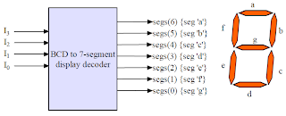
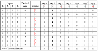
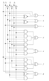
BCD to 7- segment display decoder


Truth-table


Logic Equations


Logic gates


information shared by www.irvs.info

Generate statement

• A concurrent statement used to create regular structures or conditional structures during elaboration.

• Used to create multiple copies of components , processes or blocks.

• It provides a compact description of regular structures such as memories , registers and counters.

• Two flavors of generate statement are:

– for … generate
• Number of copies is determined by a discrete range.
– if … generate
• Zero or one copy is made conditionally.

• Range must be a computable integer in any of the following forms:
– integer_expression to integer_expression.
– integer_expression downto integer_expression.
– Each integer_expression evaluates to an integer.


Syntax :

Label: for ParameterName in Range generate
[Declarations...
begin]
ConcurrentStatements...
end generate [Label];
Label: if Condition generate
[Declarations...
begin]
ConcurrentStatements...
end generate [Label];


Where:

architecture – begin - - end
block – begin - - end
generate – begin - - end


Rules :
• The Range and Condition must both be static, i.e. they cannot include signals.
• The Label at the beginning of the generate statement cannot be omitted

Synthesis:
• Synthesis is straightforward, but not all synthesis tools support generate!

Example:

architecture ABC of full_add4 is
component full_add
port (PA , PB , PC : in std_logic ;
PCOUT , PSUM : out std_logic) ;
end component ;
signal c: std_logic_vector(4 downto 0);
begin
c(0) <= cin ;
-- cin is declared in entity
GK : for k in 3 downto 0 generate
FA :full_add port map(A(k),B(k),C(k),C(k+1),SUM(k);
end generate GK ;
cout <= c(4) ;
-- cout is declared in entity
end ABC ;


infers


Another example

architecture SHIFTER_ARCH of SHIFTER is
component DFF
port (D , CLK : in std_logic ;
Q : out std_logic) ;
end component ;
begin
GK : for k in 0 to 3 generate
GK0 : IF k=0 generate
DFILPFLOP : DFF port map (count , clock , Q(k));
end generate GK0 ;
GK1_3 : if k > 0 generate
DFILPFLOP : DFF port map (Q(k-1), clock , Q(k));
end generate GK1_3 ;
end generate GK ;
end SHIFTER_ARCH ;


infers


information shared by www.irvs.info

Saturday, November 13, 2010

Top Level Entity and Lower Level Entity


A still simpler example

entity ND4 is
port (in1,in2,in3,in4 : in std_logic ;
z : out std_logic);
end ND4;
architecture ND4_CI of ND4 is
component ND2
port (a , b : in std_logic;
c : out std_logic);
end component ;
signal temp1, temp2 : std_logic;
begin
U1 : ND2 port map (a => in1 , b => in2 , c => temp1);
U2 : ND2 port map (a => in3 , b => in4 , c => temp2);
U3 : ND2 port map (a => temp1 , b => temp2 , c => z);
end ND4_CI ;


infers


information shared by www.irvs.info

Thursday, November 11, 2010

Port Map

• A port map is typically used to define the interconnection between instances in a structural description (or net list).

• A port map maps signals in an architecture to ports on an instance within that architecture.

• Port maps can also appear in a configuration or a block.

Syntax:

port map ([Formal =>] Actual, ...);
Formal = {either} Name FunctionCall
Actual = {either} Name FunctionCall open
Where:
Label : ComponentName generic map (…) ;
for - use - generic map (…) ;
block - port (…) ; ; - begin - end


Rules:

• The two forms of syntax (ordered list or explicitly named ports) can be mixed, but the ordered list must come before the named ports.

• Within an instance, the formals are ports on the component or entity being instanced, the actual are signals visible in the architecture containing the instance.

• Within a configuration, the formals are ports on the entity, the actual are ports on the component.

• If the actual is a conversion function, this is called implicitly as values are passed in.

• If the formal is a conversion function, this is called implicitly as values are passed out.

NOTE: Use the port names rather than order to improve readability and reduce the risk of making connection errors


Example:


component COUNTER
port (CLK, RESET: in Std_logic;
UpDown: in Std_logic := '0
' ;-- default value
Q: out Std_logic_vector(3 downto 0));
end component;
...
-- Positional association...
G1: COUNTER port map (
Clk32MHz, RST, open, Count);
-- Named association (order doesn't matter)...
G2: COUNTER port map ( RESET => RST,
CLK => Clk32MHz,
Q(3) => Q2MHz,
Q(2) => open,
-- unconnected
Q(1 downto 0) => Cnt2,
UpDown => open);


information shared by www.irvs.info

Wednesday, November 10, 2010

Generic Map

• Used to define the values of generics.

• Usually given in an Instance, but may also appear in a configuration.

Syntax

generic map ([Formal =>] Actual, ...)

Formal = {either} Name FunctionCall
Actual = Expression

Where :

Label : ComponentName port map (…);
for - use - port map (…)
block – generic (…); ;port – begin - end

Rules :

The two forms of syntax (ordered list or explicitly named choices) can be mixed, but the ordered list must come before the named choices.

NOTE: A generic map does not end with a semicolon!

Example:

architecture Structure of Ent is component NAND2
generic (TPLH, TPHL: TIME := 0 NS);
port (A, B: in STD_LOGIC;
F : out STD_LOGIC);
end component;
begin
G1: NAND2 generic map (1.9 NS, 2.8 NS)
port map (N1, N2, N3);
G2: NAND2 generic map (TPLH => 2 NS, TPHL => 3 NS)
port map (N4, N5, N6);
end
Structure;


information shared by www.irvs.info
Wednesday, November 3, 2010

Component Instantiation

Component

• A component is analogous to a chip socket; it gives an indirect way to use one hierarchical block within another.

• A component is instantiated within an architecture, and is associated with a (lower level) entity and architecture during elaboration using information from a configuration.

• A component declaration is similar in form to an entity declaration, in that it includes the required ports and parameters of the component.

• The difference is that it refers to a design described in a separate VHDL file.

• The ports and parameters in the component declaration may be a subset of those in the component file, but they must have the same names.

Component can be declared in the main code itself


Component can be declared in a package


Syntax :

COMPONENT component_name
GENERIC ( parameter_name : string := default_value ;parameter_name : integer := default_value);
PORT (input_name, input_name : IN STD_LOGIC;
bidir_name, bidir_name : INOUT STD_LOGIC;
output_name, output_name : OUT STD_LOGIC);
END COMPONENT;


Where :

package - - end
architecture - is - - begin - end
block - - begin - end
generate - - begin - end


Rules:

• For default configuration, the component name must match the name of the corresponding entity to be used in its place, and generics and ports must also match in name, mode and type.

Synthesis:

• A component without a corresponding design entity is synthesized as a black
box.

NOTE: In VHDL'93, components are not necessary. It is possible instead to directly instantiate an entity within an architecture.

Example

component Counter
generic (N: INTEGER);
port (Clock, Reset, Enable:inStd_logic;
Q: buffer Std_logic_vector (N-1 downto 0));
end component ;


Instantiation

• A concurrent statement used to define the design hierarchy by making a copy of a lower level design entity within an architecture.

• In VHDL'93, a direct instantiation of an entity bypasses the component and configuration.

Syntax:

InstanceLabel: [component] ComponentName
[GenericMap] [PortMap];
InstanceLabel: entity EntityName[(ArchitectureName)]
[GenericMap] [PortMap];
InstanceLabel: configuration ConfigurationName
[GenericMap] [PortMap];


Where:


architecture – begin - - end
block – begin - - end
generate – begin - - end


Rules:

• An entity, architecture or configuration must be compiled into a library before the corresponding instance can be compiled.

• However, an instance of a component can be compiled before the corresponding design entity has even been written.

Example :


G1: NAND2 generic map (1.2 ns)
port map (N1, N2, N3);
G2: entity WORK.Counter(RTL)
port map (Clk, Rst, Count);

Block

• There are two types of blocks

– Simple
– Guarded

Simple block

• The BLOCK statement, in its simple form, represents only a way of locally partitioning the code.

• It allows a set of concurrent statements to be clustered into a BLOCK, with the purpose of turning the overall code more readable and more manageable (which might be helpful when dealing with long codes).


• Block can be nested inside another block


Guarded block

• A guarded BLOCK is a special kind of BLOCK, which includes an additional expression, called guard expression.

• A guarded statement in a guarded BLOCK is executed only when the guard expression is TRUE.

Syntax

label: BLOCK (
guard expression)
[declarative part]
BEGIN
(concurrent guarded and unguarded statements)
END BLOCK label;


• Even though only concurrent statements can be written within a BLOCK, with a guarded BLOCK even sequential circuits can be constructed.

Latch
LIBRARY ieee;
USE ieee.std_logic_1164.all;
ENTITY latch IS
PORT (d, clk: IN STD_LOGIC;
q: OUT STD_LOGIC);
END latch;
ARCHITECTURE latch OF latch IS
BEGIN
b1: BLOCK (clk='1')
BEGIN
q <= GUARDED d;
END BLOCK b1;
END latch;


DFF
LIBRARY ieee;
USE ieee.std_logic_1164.all;
ENTITY DFF IS
PORT (d, clk, rst: IN STD_LOGIC;
q: OUT STD_LOGIC);
END DFF;
ARCHITECTURE DFF OF DFF IS
BEGIN
b1: BLOCK (clk’EVENT AND clk='1')
BEGIN
q <= GUARDED ‘0’ WHEN rst=‘1’ ELSE d;
END BLOCK b1;
END DFF;


information shared by www.irvs.info
Tuesday, November 2, 2010

concurrent constructs (with…select)

• A concurrent statement which assigns one of several expressions to a signal depending on the value of the expression at the top.

• Equivalent to a process containing a case statement.

Syntax

[Label:] with Expression select
Target <= [Options]
Expression [after TimeExpression] when Choices,
Expression when others;


Where to use ?

architecture – begin – HERE – end
block – begin – HERE – end
generate – begin – HERE – end


Rules:

• Every case of the Expression at the top must be covered once and only once by the choices.

• An Expression on the right hand side may be replaced by the reserved word “unaffected”.

• All possible choices must be enumerated.

• “others” clause is important since we have 9- valued logic.

• Selected signal assignments are synthesized to combinational logic.

• The Expressions on the right hand side are multiplexed onto the Target signal.

Remarks:

• Conditional and selected signal assignments are a good way to describe combinational logic in Register Transfer Level descriptions.

Example (Multiplexer)


architecture mux41 of mux is -- Assumptions
begin -- a,b,c,d,z are
with control select -- std_logic
z <= a when “00” , -- control is
b when “01” ,-- std_logic_vector(1 downto 0)
c when “10” ,
d when “11” ,
‘Z’ when others ;
end mux41 ;


information shared by www.irvs.info