IRVS VLSI IDEA INNOVATORS

IRVS VLSI IDEA INNOVATORS
VLSI Project, Embedded Project, Matlab Projects and courses with 100% Placements

Saturday, October 30, 2010

Concurrent Constructs

Types of concurrent constructs

• when … else
• with … select

NOTE: These constructs need not be in the process.

when…else

• A concurrent statement which assigns one of several expressions to a signal, depending on the values of Boolean conditions which are tested in sequence.

• Equivalent to a process containing an if statement.

Syntax

[Label:] Target <= [Options]
Expression [after TimeExpression] when Condition else
...
Expression [after TimeExpression] [when Condition];


Where to use ?

architecture – begin – HERE - end
block – begin – HERE - end
generate – begin – HERE - end


Rules:

• The reserved word guarded may only appear in a signal assignment within a guarded block. A guarded assignment only executes when the guard expression on the surrounding block is true.

• An Expression on the right hand side may be replaced by the reserved word “unaffected”.

Synthesis

• Conditional signal assignments are synthesized to combinational logic.

• The Expressions on the right hand side are multiplexed onto the Target signal.

• The resulting logic will be priority encoded, because the conditions are tested in sequence.

Remarks:

• Conditional and selected signal assignments are a concise way to describe combinational logic in Register Transfer Level descriptions, although processes can be easier to read and maintain in some cases.

• A conditional assignment is a neat way to convert from a Boolean condition to the type Std_logic.

Example

z <= a when s1=‘1’
else
b when s2=‘1’
else
c ;


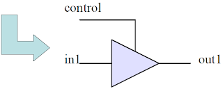
Example (Tri-state Buffer)


architecture tri_buff of tri_buff_part is
begin
out1 <= in1 when control=‘1’
else
‘z’;
end tri_buff ;


information shared by www.irvs.info

Friday, October 29, 2010

Difference in VHDL

• In VHDL the same statement will mean a feedback in a purely combinational logic which is invalid.


• VHDL code is inherently concurrent (parallel).

• Only statements placed inside a PROCESS, FUNCTION, or PROCEDURE are sequential.

• Concurrent code is also called data flow code.

• Order does not matter.

• We can only build combinational logic circuits with concurrent code.

• Concurrent assignment produces one driver for each assignment statement.


Multiple driver assignment


information shared by www.irvs.info

Thursday, October 28, 2010

Delays in VHDL

• In VHDL, there are three types of delay that are encountered.

– Inertial delay
– Transport delay
– Delta delay


Inertial Delay

• Inertial delay is the default in VHDL.

• Behaves similarly to the actual device.

• Output signal of the device has inertia, which must be overcome for the signal to change value.

• The inertial delay model is by far the most commonly used in all currently available simulators.


Transport Delay

• It represents a wire delay in which any pulse, no matter how small, is propagated to the output signal delayed by the delay value specified.

• Especially useful for modeling delay line devices, wire delays on a PCB, and path delays on an ASIC.


Delta delay

• These are used since the PC that processes and simulates a concurrent phenomenon is basically a sequential machine.

• The simulation program mimics concurrency by scheduling events in some order.

• Simulation deltas are used to order some types of events during a simulation.

• Specifically, zero delay events must be ordered to produce consistent results.


information shared by www.irvs.info

Wednesday, October 27, 2010

Generics

• As the name suggests, GENERIC is a way of specifying a generic parameter.

• A static parameter that can be easily modified and adapted to different applications.

• The purpose is to make the code more flexible and reusable.

• must be declared in the ENTITY.

• More than one GENERIC parameter can be specified in an ENTITY.

Syntax

GENERIC (parameter_name : parameter_type := parameter_value);

Example

The GENERIC statement below specifies a parameter called n, of type INTEGER, whose default value is 8. Therefore, whenever n is found in the ENTITY itself or in the ARCHITECTURE (one or more) that follows, its value will be assumed to be 8.

ENTITY

ENTITY my_entity IS
GENERIC (n : INTEGER := 8; vector: BIT_VECTOR := "00001111");
PORT (...);
END my_entity;
ARCHITECTURE my_architecture OF my_entity IS
...
END my_architecture;


ARCHITECTURE

ARCHITECTURE generic_decoder OF decoder IS
BEGIN
PROCESS (ena, sel)
VARIABLE temp1 : STD_LOGIC_VECTOR (x'HIGH DOWNTO 0);
VARIABLE temp2 : INTEGER RANGE 0 TO x'HIGH;
....


information shared by www.irvs.info

Tuesday, October 26, 2010

Attributes

• An attribute is data that are attached to VHDL objects or predefined data about VHDL objects.

• Examples are the current drive capability of a buffer or the maximum operating temperature of the device.

• Types are
– Data Attributes
– Signal Attributes
– User-defined Attributes


Data Attributes

The pre-defined, synthesizable data attributes are the following:
• d’LOW : Returns lower array index
• d’HIGH : Returns upper array index
• d’LEFT : Returns leftmost array index
• d’RIGHT : Returns rightmost array index
• d’LENGTH : Returns vector size
• d’RANGE : Returns vector range
• d’REVERSE_RANGE: Returns vector range in reverse order


Example
Consider the following signal:
SIGNAL d : STD_LOGIC_VECTOR (7 DOWNTO 0);
Then:
d'LOW=0, d'HIGH=7, d'LEFT=7, d'RIGHT=0,
d'LENGTH=8, d'RANGE=(7 downto 0),
d'REVERSE_RANGE=(0 to 7)


If the signal is of enumerated type, then:
• d’VAL(pos) : Returns value in the position specified
• d’POS(value) : Returns position of the value specified
• d’LEFTOF(value) : Returns value in the position to the left of the value specified
• d’VAL(row, column) : Returns value in the position specified; etc


NOTE:There is little or no synthesis support.
for enumerated data type attributes

Signal Attributes

Let us consider a signal s
Then:
• s’EVENT : Returns true when an event occurs on s
• s’STABLE : Returns true if no event has occurred on s
• s’ACTIVE : Returns true if s = ‘1’
• s’QUIET


Example
All four assignments shown below are synthesizable
and equivalent. They return TRUE when an event (a
change) occurs on clk, AND if such event is upward
(in other words, when a rising edge occurs on clk)

IF (clk'EVENT AND clk='1')... -- EVENT attribute-- used with IF
IF (NOT clk'STABLE AND clk='1')... -- STABLE --attribute used
-- with IF
WAIT UNTIL (clk'EVENT AND clk='1'); -- EVENT --attribute used
-- with WAIT
IF RISING_EDGE(clk)... -- call to a function


User-defined Attributes

• VHDL also allows the construction of user-defined attributes.
• To employ a user-defined attribute, it must be declared and specified.

Attribute Declaration:

ATTRIBUTE attribute_name: attribute_type ;

Attribute Specification:

ATTRIBUTE attribute_name OF target_name: class IS value;

where:

attribute_type: any data type (BIT, INTEGER, STD_LOGIC_VECTOR, etc.)
class: TYPE, SIGNAL, FUNCTION, etc.
value: ‘0’, 27, ‘‘00 11 10 01’’, etc.


Example

ATTRIBUTE number_of_inputs: INTEGER;
ATTRIBUTE number_of_inputs OF nand3: SIGNAL IS 3;
...
inputs <= nand3'number_of_inputs; -- attribute call, -- returns 3


information shared by www.irvs.info

Saturday, October 23, 2010

Classes

• Each object has a data type and class.

• Class indicates how the object is used in the module and what can be done with that object.

• Type indicates what type of data the object contains.

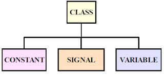
• Each object belongs to one of the following class:
– CONSTANT
– SIGNAL
– VARIABLE


Constants

• These are identifiers with fixed values.

• The value is assigned only once when declared.

• Values cannot be changed during simulation

CONSTANT bus_width : INTEGER :=16 ;
CONSTANT CLK_PERIOD : TIME :=15 ns ;


• Constants make the design description more readable.

• Design changed at later time becomes easy.

Signals

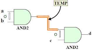
Equivalent to wires within a circuit


Example:

architecture and_gate of myand is
signal TEMP : STD_LOGIC ;
begin
U1 : AND2 portmap ( a, b, TEMP ) ;
U2 : AND2 portmap (TEMP, c , d ) ;
end and_gate ;


• Thus signals are used :

– to connect design entities together and communicate changes in values within a design
– instead of INOUT mode


• Each signal has a history of values i.e. they hold a list of values which include current value of the signal and a set of possible future values that can appear on the signal.

• Computed value is assigned to signal after specified delay called DELTA DELAY.

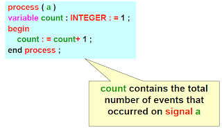
Variables

• These are objects with single current value.

• They are used to store the intermediate values between the sequential statements.

• Variable assignment occurs immediately.

• Variables can be declared and used inside the process statement only. But they retain their value throughout the entire simulation.

Example :


information shared by www.irvs.info

Friday, October 22, 2010

Operator overloading

• Operators can be user-defined.

• Let us consider the pre-defined arithmetic operators seen earlier (+,- , *, /, etc.). They specify arithmetic operations between data of certain types (INTEGER, for example).

• For instance, the pre-defined ‘‘+’’ operator does not allow addition between data of type BIT.

• We can define our own operators, using the same name as the pre-defined ones.

• For example, we could use ‘‘+’’ to indicate a new kind of addition, this time between values of type BIT_VECTOR. This technique is called operator overloading.

• Example: Consider that we want to add an integer to a binary 1-bit number. Then the following FUNCTION could be used.

FUNCTION "+" (a: INTEGER, b: BIT) RETURN INTEGER IS
BEGIN
IF (b='1') THEN RETURN a+1;
ELSE RETURN a;
END IF;
END "+";


A call to the function above could thus be the
following:

SIGNAL inp1, outp: INTEGER RANGE 0 TO15;
SIGNAL inp2: BIT;
(...)
outp <= 3 + inp1 + inp2;
(...)


• In ‘‘outp<=3+inp1+inp2;’’, the first ‘‘+’’ is the pre- defined addition operator (adds two integers), while the second is the overloaded user-defined addition operator (adds an integer and a bit).


information shared by www.irvs.info

Wednesday, October 20, 2010

operators

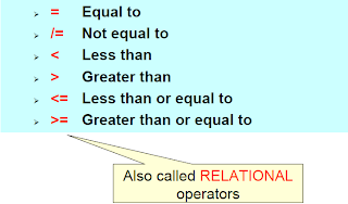
Comparison operators


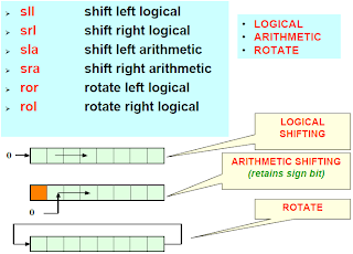
Shift operators


Concatenation operator

• Operands can be one-dimensional array type or element type
• “ &” works on vectors only
& Concatenation

Example:

SIGNAL a : STD_LOGIC_VECTOR ( 5 DOWNTO 0 ) ;
SIGNAL b,c,d : STD_LOGIC_VECTOR ( 2 DOWNTO 0 ) ;
BEGIN
b <= ‘0’ & c(1) & d(2) ;
a <= c & d ;


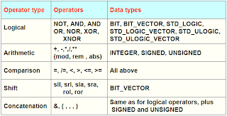
Operator summary


information shared by www.irvs.info

Tuesday, October 19, 2010

Operators

• VHDL provides several kinds of pre- defined operators
– Assignment operators
– Logical operators
– Arithmetic operators
– Relational operators
– Shift operators
– Concatenation operators

Assignment operators

• Are used to assign values to signals, variables, and constants.


Then the following assignments are legal:

x <= '1'; -- '1' is assigned to SIGNAL x using "<="
y := "0000"; -- "0000" is assigned to VARIABLE y using --":="
w <= "10000000"; -- LSB is '1', the others are '0'
w <= (0 =>'1', OTHERS =>'0'); -- LSB is '1', the others -- are '0'


Logical operators

• Used to perform logical operations.

• The data must be of type:
– BIT, STD_LOGIC
– STD_ULOGIC
– BIT_VECTOR
– STD_LOGIC_VECTOR
– STD_ULOGIC_VECTOR


Arithmetic operators

• Used to perform arithmetic operations. The data can be of type INTEGER, SIGNED, UNSIGNED, or REAL (the last cannot be synthesized directly).

• Also, if the std_logic_signed or the std_logic_unsigned package of the ieee library is used, then STD_LOGIC_VECTOR can also be employed directly in addition and subtraction operations.


• There are no synthesis restrictions regarding addition and subtraction, and the same is generally true for multiplication.

• For division, only power of two dividers (shift operation) are allowed.

• For exponentiation, only static values of base and exponent
are accepted.

• Regarding the mod and rem operators, y mod x returns the remainder of y/x with the signal of x, while y rem x returns the remainder of y/x with the signal of y.

• Finally, abs returns the absolute value.

information shared by www.irvs.info

Thursday, October 14, 2010

Categories of data types (VHDL)

User defined data types

• VHDL allows user defined data types.

• Two categories of this data type are:

– Integer
– Enumerated

• User defined integer type

TYPE my_integer IS RANGE -32 to +32 ;
TYPE student_grade IS RANGE 0 to 100 ;


• User defined enumerated type


TYPE my_logic IS (‘0’, ‘1’, ‘Z’);
TYPE my_state IS ( idle, forward, backward, stop) ;


• The encoding of enumerated types is done sequentially and automatically.

• Since here there are 4 states only two bits are required hence “00” is assigned to first state ( idle), “01” to second state (forward) and so on.

Subtypes

• A SUBTYPE is a TYPE with a constraint.

• Though operations between data of different types are not allowed, they are allowed between the subtype and its corresponding base type.
SUBTYPE sub_state IS my_state RANGE idle to backward ;

This means that the subtype
sub_state =(idle, forward, backward)

Arrays

• Arrays are collections of objects of same type.

• Can be 1-dimensional, 2-dimensional or
1D X 1D.

• Higher dimensional arrays are possible but not synthesize.


Array syntax

To specify an array :
TYPE type_name IS ARRAY (specification) OF data_type ;

To use an array :
SIGNAL signal_name : type_name [:= initial_value]

Example : 1D x 1D array
– We want to build an array containing 4 vectors, each of size 8 bits.
– we will call each vector as row and the complete array as matrix.


Example : 2D array
– This array will be created with scalars only.


Port Arrays

• In the specification of the input or output pins (PORTS) of a circuit (which is made in the ENTITY), we might need to specify the ports as arrays of vectors.

• Since TYPE declarations are not allowed in an ENTITY, the solution is to declare user-defined data types in a PACKAGE, which will then be visible to the whole design (thus including the ENTITY)


• As can be seen in the example above, a user- defined data type, called vector_array,was created, which can contain an indefinite number of vectors of size eight bits each (NATURAL RANGE <> signifies that the range is not fixed, with the only restriction that it must fall within the NATURAL range, which goes from 0 to +2,147,483,647)

• The data type was saved in a PACKAGE called my_data_types, and later used in an ENTITY to specify a PORT called inp.

• Notice in the main code the inclusion of an additional USE clause to make the user-defined package my_data_types visible to the design.

Records

• Records are similar to arrays, with the only difference that they contain objects of different types.


Signed and Unsigned data types

• These types are defined in the std_logic_arith package of the ieee library.


• An UNSIGNED value is a number never lower than zero. For example, ‘‘0101’’
represents the decimal 5, while ‘‘1101’’ signifies 13.

• If type SIGNED is used instead, the value can be positive or negative (in two’s complement format). Therefore,‘‘0101’’ would represent the decimal 5, while ‘‘1101’’ would mean 3.

• To use SIGNED or UNSIGNED data types, the std_logic_arith package, of the ieee library, must be declared.

information shared by www.irvs.info
Tuesday, October 12, 2010

Data Types VHDL

• In order to write VHDL code efficiently it is necessary to study the specification and use of data types.

• Following are the categories of data types:
– Pre-defined
– User defined
– Subtypes
– Arrays
– Port arrays
– Records
– Signed and unsigned

Pre-defined data types

• Specified by IEEE 1076 and IEEE 1164


• To assign a value to the signal use the operator “ < = ”

• Assignment examples:


• Other types


information shared by www.irvs.info
Friday, October 8, 2010

Language Elements of VHDL

• VHDL is a strongly typed language.
– Designers have to declare the type before using it.

• VHDL is not case sensitive ( but avoid mixed cases as a good programming practice)

• VHDL supports a wide variety of data types and operators.
– OBJECTS
– OPERATORS
– AGGREGATES

Objects

• They are used to represent and store the data in the design being described.

• Object contains a value of specific type.


This results in an object called COUNT that holds INTEGER value that belongs to class SIGNAL.

• The name given to the object is called as identifier.

• Do not use reserved words as identifiers.

• Each object has a data type and class.

• Class indicates how the object is used in the module and what can be done with that object.

• Type indicates what type of data the object contains.

• Each object belongs to one of the following class:
– CONSTANT
– SIGNAL
– VARIABLE
– FILES


information shared by www.irvs.info
Thursday, October 7, 2010

Architecture of VHDL

It specifies

• Behaviour
• Function
• Relationship between inputs and outputs of an entity

Syntax


• Architecture can contain only concurrent statements.
• A design can be described in an architecture using various levels of abstraction.
• An entity can have more than one architectures since a function can be implemented in a number of ways.
• There can be no architecture without an entity.

Architectural bodies

• Behavioural

– It is the high-level description.
– It contains a set of assignment statements to represent behaviour.
– No need to focus on the gate-level implementation of a design.


• Dataflow

–It uses concurrent signal assignment statements.


• Structural

– Components from libraries are connected together.
– Designs are hierarchical.
– each component can be individually simulated.
– it makes use of component instantiation.


Configuration

• Since a number of architectures can exist for an entity , using configuration statement we can bind a particular architecture to the entity.

Syntax


information shared byc

Tuesday, October 5, 2010

Friday, October 1, 2010

Entity

– It is the design’s interface to the external circuitry.

– Equivalent to pinout /package of an IC.

– VHDL design must include one and only one entity per module.

– It can be used as a component in other entities after being compiled into a library.

Entity declaration

• Defines the input and output ports of the design.

• Name of the entity can be anything other than the reserved VHDL word.

• Each port in the port list must be allotted:
– a name ( should be self-explanatory that provides information about its function.
– data flow direction or mode.
– a type.

• Ports should be well documented with comments at the end of line providing additional information about the signal.

Entity syntax

entity entity_name is
port ( port_name : signal_mode signal_type ;
port_name : signal_mode signal_type ;
port_name : signal_mode signal_type );
end entity_name ;

information shared by www.irvs.info