• FUNCTIONAL SIMULATION
• BEHAVIORAL SIMULATION
• STATIC TIMING SIMULATION
• GATE-LEVEL SIMULATION
• SWITCH-LEVEL SIMULATION
• TRANSISTOR-LEVEL OR CIRCUIT- LEVEL SIMULATION
• FUNCTIONAL SIMULATION
It ignores timing aspects.
Verifies only the functionality of the design.
• BEHAVIORAL SIMULATION
A given functionality is modeled using HDL.
Timing aspects are considered.
• STATIC TIMING SIMULATION
A built in tool that computes delay for each timing path
Does not require input stimuli.
• GATE-LEVEL SIMULATION
Is used to check the timing performance of design
Delay parameters of logic cells are used to verify things.
• SWITCH-LEVEL SIMULATION
Is one level below the gate level simulation.
It models transistors as switches.
It provides more accurate timing predictions than gate-level simulation.
• TRANSISTOR-LEVEL SIMULATION
Requires transistor models. Circuit is described in terms of resistances, capacitances and voltage and current sources.
A set of mathematical equations relating current and voltages is setup and solved numerically.
Gives analog results and is most accurate.
Requires large amount of computing resources.
Simulation time depends on :
• Simulation levels of logic
• Physical Memory of PC
• Speed of PC
information shared by www.irvs.info
VLSI IDEA INNOVATORS are an R&D organization who were in to research and development in the electronics field for many number of years .Now we are getting to training process with the syllabus structured in R&D manner . This is the 1st time in India an R&D organization getting in to training process.
Thursday, January 13, 2011
TYPES OF SIMULATION
DELAY MODELING
Delays are timing parameters given by the user for modeling physical characteristics of hardware.

Delays are specified in signal assignment statements only.
Delays should NOT be used in variable assignments.
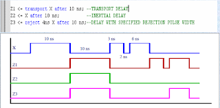
INERTIAL DELAY
• It is used to model the inherent inertia of physical devices.
• Example:
– The input value must be stable for a specified minimum pulse duration before the value is allowed to propagate to the output.
– If the input is not stable for the specified limit, no output change occurs.
TRANSPORT DELAY
• It represents pure propagation delay i.e., wires and interconnect delays.
• Signal value is assigned with a specified delay independent of the width of the input waveform.
DELAYS

information shared by www.irvs.info

Delays are specified in signal assignment statements only.
Delays should NOT be used in variable assignments.
INERTIAL DELAY
• It is used to model the inherent inertia of physical devices.
• Example:
– The input value must be stable for a specified minimum pulse duration before the value is allowed to propagate to the output.
– If the input is not stable for the specified limit, no output change occurs.
TRANSPORT DELAY
• It represents pure propagation delay i.e., wires and interconnect delays.
• Signal value is assigned with a specified delay independent of the width of the input waveform.
DELAYS

information shared by www.irvs.info
Subscribe to:
Comments (Atom)